How is your own Aural ID HRTF profile created

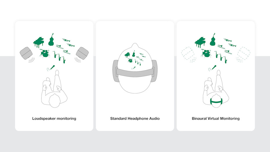
Loudspeakers span a sound stage
When listening to stereo or immersive audio through loudspeakers, we perceive sound not only coming from the loudspeakers but also appearing in the space between the loudspeakers. The area where the sound appears is known as the sound stage, and when sound sources appear outside of the physical loudspeakers on the sound stage, we refer to these sound sources as virtual sound images.
The sound stage and virtual sound images exist because of the human directional hearing mechanism that allows us to understand where different sounds are coming from. Stereo and immersive sound systems exploit this mechanism to create the impression of a space where individual performers and sounds exist are happening, on the sound stage in the space between the actual loudspeakers as virtual sound images.
Headphones eliminate directional hearing
Headphones offer undeniable advantages: isolation from outside noise is possible, portability is excellent, extended dynamic range is easily available, and headphones offer the ability to work anywhere, despite the acoustic quality of a room. However, headphones come with a fundamental limitation. Headphones deliver sound directly into the ears, disabling our directional hearing mechanism as head-related changes and influences on sound cannot occur. The brain does not understand this situation, so headphone sound typically appears inside the head.
Lack of access to directional hearing prevents and limits those audio engineering tasks that employ the human directional hearing mechanism. These include compositing the sound stage elements by panning and blending instruments, vocals and effects on the sound stage and working reliably with the audible space.
Directional hearing mechanisms
Unconscious mechanisms in our brains help us understand the direction of sound. The brain decodes the sound direction from small consistent changes arising when sound interacts with our body before reaching the ear canal entries. Sound is analysed by three main mechanisms.
First, there are the benefits of having two ears.
Most sound reaches the left and right ears at slightly different times, because the ears are physically separated by the width of the head, so sound has a shorter path to the nearer ear. The difference in time is extremely small, typically measured in microseconds, but the auditory brainstem can compare the timing of waveform features with remarkable precision. This time delay is not constant but varies slightly with frequency. This interaural time difference (ITD) is important for understanding the direction of low-frequency sounds, where the wavelength is long enough so that timing comparisons between the ears remain unambiguous.
Sound usually arrives at the ears with different intensity. The main reason for this is that the head acts as an acoustic barrier, particularly for higher frequencies. When sound comes from one side, the far-side ear sits in an acoustic shadow of the head, receiving a weaker signal. This interaural level difference (ILD) increases with frequency because shorter wavelengths are more easily blocked or attenuated by the head. The brain interprets left-right intensity asymmetries as cues for direction.
Using the differences between the two ears to detect direction of sound comes with some caveats. Notice that when sound arrives from directly in front, above or behind you on the front-back plane dividing the head, the distances to and levels at the left and right ears are the same. Then, interaural timing and level differences are zero and do not contribute to detecting the direction of sound.
In this situation, the third mechanism of sensing sound direction kicks in, where localisation is determined using direction-dependent sound colour as the cue. This third method of detection works because the human body causes sound to be filtered differently depending on direction. The upper torso, head and outer ear (in Latin, pinna) all reflect and diffract sound. The pinna has a complex shape of folds and cavities that reflect and diffract sound particularly at high frequencies. The interactions of the reflected and diffracted sound create direction-specific patterns of reinforcement and cancellation of sound at certain frequencies and affect frequency-dependent timings of sound arrivals, effectively imprinting a spectral signature onto the sound entering the ears. This also means that having only one ear already gives ability to localise sound.
Normally, these three mechanisms work together, each contributing to our understanding of the direction of sound. The brain learns to interpret timing, level difference and spectral colouration through experience. Over time we build an internal unconscious mapping from these patterns to directions in space. This mapping is not consciously accessible and significantly operates in the brainstem and midbrain, with higher auditory areas refining the percept into a stable sense of direction. Even if the directional hearing mechanism significantly exploits sound colour, on the conscious level we mostly do not recognise sound colour variations when sound direction changes.
Note that distance perception is also partly encoded in these cues, but less directly. As sound travels farther, high frequencies are absorbed more by air, and reflections from the environment increase in level relative to the direct sound. The brain interprets the relative reduction in the high-frequency level, change in direct-to-reverberant sound level and overall change in sound intensity as distance.

Your body shape enables directional hearing
Let’s walk through how various body parts contribute to your Head-Related Transfer Function (HRTF).
Your own maximum ITD depends on your head size and is one of the unique personal features.
Assume a sound is arriving from one side. An adult's ears are separated by 18–22 cm, and sound reaches the nearer ear earlier than the farther one. While an average-sized adult head causes the maximum delay between the ears to be about 600 to 700 microseconds, typical head width varies between males and females. Adult female heads commonly measure around 14–16 cm in width, while adult male heads measure around 15.5–18 cm. The resulting range of maximum ITD is about 550–600 microseconds for females and about 620–700 microseconds for males. The brain, particularly nuclei in the brainstem like the medial superior olive, is sensitive to these tiny timing disparities and uses them as a cue for left–right position. This mechanism works best for lower frequencies, where the waveform is slow enough for timing comparisons. In the HRTF, this feature appears as the interaural time difference (ITD).
For high-frequency sounds, the brain relies on intensity differences to understand direction of sound. The head shape blocks and attenuates sound, especially at higher frequencies with shorter wavelengths. The ear behind the head, farther from the source, receives a quieter and spectrally less bright sound. This creates a level difference which may reduce high frequencies by 20 dB or more. The lateral superior olive is heavily involved in processing these level differences. In the HRTF, this second major effect for judging direction of sound appears as the interaural level difference (ILD) in HRTF. ILD is close to zero at low frequencies but increases to 10-20 dB at several kilohertz, where the head casts a strong acoustic shadow. Your head size determines where in frequency these shadowing effects kick in.
These two cues can determine if sound is coming from the left or right but do not uniquely resolve elevation or whether a sound is in front or behind. For this, outer ear (pinna) structures and shapes become crucial. Pinna ridges and cavities create direction-dependent filtering as sound reflects and diffracts around these shapes. Certain frequencies are boosted while others are attenuated. The exact pattern of spectral peaks and notches changes with the vertical angle and is different for front/back positions of the source.
At the lowest audible frequencies, below roughly 200 Hz, where the sound wavelength in air is about 1.5 metres or 5 feet, the wavelengths are longer than the width of the head and even the shoulders, so sound essentially wraps around the entire body with very little change. In this region, the head produces almost no acoustic shadowing, and interaural level differences are negligible. Directional information comes almost entirely from interaural time differences created by the spacing between the ears. The torso can introduce very broad, gentle effects due to reflections, but these effects are subtle and not sharp in frequency.
In the low mid frequencies, roughly 200 Hz to 1.5 kHz, wavelengths become comparable to head size. Now the head becomes an obstacle, but diffraction around the head remains strong. Interaural time differences remain the dominant cue, but interaural level differences start to emerge. The torso and shoulders contribute more here, creating broad spectral shaping, helping with elevation sensing.
In the upper midrange, 1.5 kHz to 4 kHz, the head becomes a significant acoustic barrier. This is where interaural level differences become strong and reliable, because the far ear sits now in a significant acoustic shadow.
Superimposed on these binaural differences are the monaural spectral features created primarily by the pinna structure and shape, giving an ability to judge direction of sound with only one ear. These time delayed reflections, created by your pinna shape details on the order of tens to a few hundred microseconds after the direct sound, are probably the most personal feature of your unique HRTF.
Above roughly 4–5 kHz, the outer ear (pinna) becomes the dominant source of directional filtering. The fine structures of the pinna (ridges like the helix and antihelix, and cavities like the concha) are on the scale of centimetres. These structures create interference patterns through reflection and diffraction, producing narrowband increases (peaks) and reductions (notches) in certain frequencies, and the exact peak and notch frequencies shift depending on the direction of sound arrival. This frequency region is where the most detailed personal fingerprints, a person’s individual and unique features in the HRTF, are formed. At higher frequencies, above 8–10 kHz, pinna-induced spectral features become more pronounced and remain highly listener-specific. Differences in ear shape can shift notch frequencies by significant amounts.
The ear canal leading to the eardrum adds an acoustic resonance, boosting frequencies around 2–4 kHz regardless of sound direction before sound reaches the eardrum. While this doesn’t encode direction, it interacts with the direction-specific features and shapes the overall spectrum reaching the eardrum and eventually the inner ear.
Your brain continuously recalibrates itself to detect direction using the specific filtering characteristics of your ears and head shape. If the shape of the pinna is suddenly altered, people initially lose some ability to localise but usually relearn it over time, demonstrating that the interpretation of direction-dependent changes in HRTF are learned rather than hardwired.
Resolution of directional hearing
The smallest change in a sound’s direction producing reliable detectable perceptual change is called the minimum audible angle (MAA). It is not a fixed number. MAA depends on the direction of sound and what cues in the sound are available for understanding direction.
In the azimuth plane (left–right direction along the horizontal plane), MAA performance is the best directly in front of the listener. Directly in front, under ideal conditions with broadband signals, the MAA is typically about 1–2°. This very fine resolution is because both ITD and ILD are changing most rapidly with angles close to the midline, resulting in small shifts of source direction producing large cue changes. When the sound source moves toward the sides, this sensitivity degrades. Directly on one side (at 90° azimuth), the MAA increases to 5–10° or more, because in that direction binaural cues change slowly with angle and head movements produces small cues in ITD and ILD.
Resolving direction for sound arriving in higher or lower elevations, above or below the ear height, is less precise. Detection uses mainly spectral cues created in the pinna structures, while ITD and ILD reduce with elevation increase. With broadband stimuli, the MAA generally reduces to about 5–10° in the frontal field.
Frequency content matters a lot here. Low-frequency sound can support fine discrimination near the midline particularly in azimuth. High-frequency sounds relying more on level differences can be detected quite precisely when sounds contain transients. However, when the sound is close to a continuous pure tone, localisation becomes worse due to ambiguities in both timing and spectral cues.
There are regions of poorer performance. Because the directional cues change less, elevation judgments are less reliable for sounds directly in front versus slightly to the side. Also front–back confusions are more common when many sound directions share similar binaural cues and must be disambiguated purely by pinna filtering. Head movements can enhance directional detection performance by enabling dynamic changes in cues, and this helps resolve ambiguities.

The fingerprint of your hearing – HRIR and HRTF
Head-related impulse response (HRIR) and the head-related frequency response (HRTF) are closely related and describe the same phenomenon in different domains.
Head-related impulse response (HRIR) is the time-domain result of sound reaching your ears from a particular direction. An HRIR contains several recognisable features. The earliest part of the HRIR is the direct sound arrival. Its time differs slightly between the two ears depending on sound direction. After that, a series of small reflections and diffractions are caused by the pinna, head and torso, and these appear as delayed, lower-amplitude components. All of these happen when sound hits various parts of your anatomy.
The head-related impulse response length in time is limited by the physical size of your upper body. The HRIR can be understood as a finite impulse response filter with length of less than 2 milliseconds. This time span includes all head and body related acoustic effects to the distance of about 0.7 meters from the ear canal entry. Each direction of sound in space corresponds to a unique such filter.
Fourier transform is a mathematical tool that converts a signal expressed as a function of time into one expressed as a combination of sinusoidal waves (frequency components). Each frequency component has a certain magnitude and phase.
When you take the Fourier transform of an HRIR, you obtain the head-related transfer function (HRTF). It is the frequency-domain description of how sound from a specific direction is filtered by the listener’s anatomy before it reaches the eardrum. For each frequency, it tells how much sound is amplified or attenuated and how its phase is shifted. Magnitude variations cause the sound level to increase and decrease at certain frequencies, and phase variations delay the sound by varying amounts at certain frequencies. For example, a sound coming from above might introduce a sharp reduction of sound level (notch) at a certain high frequency, while a sound from ear level shifts that notch elsewhere in frequency.
While the HRIR is a real-valued quantity, expressing the sound pressure at different moments of time as sound arrives at the ears, the HRTF is complex valued, having certain magnitude and phase at each frequency. The magnitude of HRTF describes at each frequency how much sound is amplified or attenuated by the anatomy for that direction. The HRTF phase describes the frequency-dependent timing of sound introduced by sound propagation, reflections and diffractions.
The HRTF magnitude is the typical graph shown. At low frequencies, the HRTF magnitude changes smoothly because wavelengths are large relative to human anatomy. At higher frequencies, narrow peaks and deep notches appear due to interference effects generated by the head and pinna.
The HRTF phase response is rarely printed but contains both the gross interaural propagation delay (ITD) and more subtle frequency-dependent delay variation caused by acoustic diffractions and reflections.
The personal Aural ID HRTF Profile represents your own way of hearing direction of audio. It describes how your head, external ear and upper body affect audio arriving from a given direction and is totally unique to you. When we process an audio signal with your own HRTF of a certain direction in azimuth and elevation and present this to you on headphones, you will hear the sound located in that direction relative to your head and outside of your head.
This is why using someone else’s HRTF or an HRTF of a head-and torso simulator (dummy head), will not be fully understandable to your brain, and this often leads to degradations, such as degraded localisation, front-back confusions, and sound colour problems.
It is worth noting that the auditory system continuously relearns its HRTF over time. This enables listeners to somewhat adapt to foreign HRTFs. The auditory system is plastic enough to learn interpretations of initially unfamiliar spatial cues. However, there is strong evidence that a listener’s own HRTF remains the perceptual optimum because it matches the listener’s anatomy and continues to be reinforced by lifelong multisensory calibration in the brain.
The consequences of using a foreign HRTF include changes in sound direction understanding and direction-dependent changes in the understanding of the sound colour. The sound colour confusion is easy to accept once we recognise that directional hearing apparatus exploits direction-specific colourations as cues to sound direction. This process is largely unconscious but when the mismatch to the expectation of the hearing system becomes large because of using a foreign HRTF, the colourations can become audible at the conscious level. The difference between your own HRTF and the foreign HRTF must be sufficiently large for this to happen. When using a foreign HRTF, the horizontal localisation usually remains reasonably good because the dominant cues for azimuth are governed by head geometry and are relatively similar across adults. Problems become more apparent in elevation perception, front-back discrimination, externalisation, and timbral naturalness. At the extreme, when listeners are initially exposed to a foreign HRTF that is too different from the person’s actual HRTF, sound may internalise inside the head and broadband sounds can acquire an unnatural colouration.
Adaptation to a foreign HRTF can occur relatively fast. The first improvements can emerge within hours, especially when the listener can move the head and the HRTF processing responds accordingly. Over days to weeks of repeated exposure, listeners can significantly improve in localisation accuracy. Elevation performance recovers, front-back confusions decrease, and externalisation becomes more stable. However, even after extensive training, performance with a foreign HRTF rarely becomes indistinguishable from performance with the listener’s own HRTF, especially in demanding tasks involving precise elevation and timbre judgement.
How to obtain the HRTF
There are several ways to obtain a person’s HRTF, ranging from direct acoustic measurement and exact computational estimation using the physics of sound propagation, to various ways of selecting the most likely HRTF or a set of likely HRTF features.
An approximate HRTF can be determined using anthropometric estimation, where a system predicts or selects the most likely HRTF. This can be a selection from an existing data set of HRTFs or synthesises of an HRTF likely to match what is known about a listener's anatomy, such as head width, pinna dimensions, shoulder size, or ear photographs. This approach does not actually measure the HRTF, but uses statistics and maximises likelihoods, drawing on known statistical relationships between anatomy and HRTF features. Machine learning, principal component models and regression techniques are commonly used. These approaches may be faster than full measurement or full simulation of acoustics, but do not deliver a person’s actual HRTF.
The best accuracy can be obtained with a person’s own HRTF. The direct method of acquiring the HRTF information is acoustic measurement using microphones placed at the ear canals. Tiny probe microphones are positioned either at the blocked ear canal entrance or inside the canal near the eardrum. The listener sits in an acoustically controlled environment, usually an anechoic chamber, while sound is emitted from all the directions of interest.
The second main approach for obtaining an accurate HRTF is listener geometry-based numerical simulation of acoustics of the 3D body shape. Here, the listener’s anatomy is first captured as a detailed 3D model using techniques such as photogrammetry, laser scanning, structured-light scanning, MRI, or even CT imaging. The resulting geometric model should include the pinnae, head, neck, shoulders and upper torso. Once the geometry is obtained, acoustic wave propagation across this object is then simulated numerically using methods that model the fundamental wave propagation for sound, such as the boundary element method, finite element method, or finite difference time domain simulation. In this computation, virtual sound sources are placed around the model in the directions where we want to find the HRTF, and the resulting sound pressure at the left and right ears is computed. Depending on the computational approach selected, this results in HRIRs or directly in HRTFs.
How Genelec creates your own Aural ID HRTF Profile
Genelec’s Aural ID methodology determines your HRTF using visual geometry. The process begins with image acquisition using the Aural ID Creator mobile app. The user records a 360-degree video of the head, ears, shoulders, and upper torso using a smartphone camera. The video captures the external geometry from multiple viewpoints, allowing processing to reconstruct a detailed three-dimensional representation of the listener’s anatomy. The reconstruction particularly emphasises the outer ears, since the pinna geometry is the dominant contributor to high-frequency directional filtering and elevation cues.
Your accurate 3D shape is extracted using photogrammetry. Photogrammetric shape reconstruction from video footage uses the fact that the same physical object is observed repeatedly from slightly different viewpoints as the camera moves. A video footage contains a dense sequence of overlapping images, and this overlap provides the geometric redundancy needed to infer three-dimensional structure through parallax.
The first stage of the photogrammetric process is frame extraction. The video is sampled into individual images. Reconstruction system selects frames separated by sufficient viewpoint change while still maintaining strong overlap. The reconstruction begins with feature detection and matching. Distinctive visual patterns are identified in each frame. These may include corners, texture patches, skin pores, hair boundaries, ear contours, fabric texture, or shading transitions.
Once features are detected, corresponding points across multiple frames are found. If a point on the ear appears in several images, the relative displacement of that point between views encodes depth information through perspective geometry.
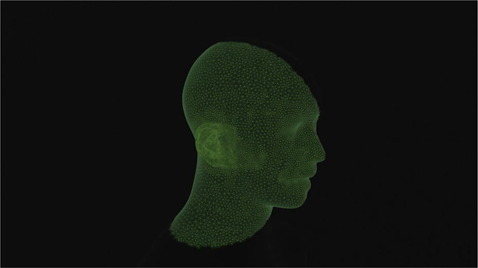
The next stage is camera pose estimation, usually called ‘structure from motion’. The algorithm estimates the three-dimensional positions of the matched points and the position and orientation of the camera for every image. Triangulation is the underlying geometric principle. Each matched image point defines a ray extending from the camera centre into space. The intersection of rays from multiple viewpoints estimates the three-dimensional location of the corresponding surface point. Repeating this process across many correspondences produces a point cloud representing the overall geometry. The point cloud is then converted into a surface mesh describing your 3D shape.
When reconstructing a human head and torso for acoustics, several factors become critically important because geometric errors can produce acoustic consequences, especially at high frequencies. The first major factor is image resolution. Fine anatomical structures such as the folds of the pinna may only be millimetres or centimetres wide. To reconstruct these accurately, particularly the ear region must occupy enough pixels in the video images. The second factor is viewpoint coverage. The shape reconstruction requires that each surface region can be observed from multiple sufficiently separated angles. Ears are particularly challenging because they contain self-occluding cavities and folds. If the video does not include strong side and rear views, large portions of the pinna geometry may remain poorly constrained or entirely invisible. To avoid this the Creator app guides the video shooting and automatically turns on the camera light to reduce shadow problems.
Camera motion quality strongly influences the quality of reconstruction. Smooth camera motion with gradual slow enough viewpoint changes produces reliable feature tracking and robust triangulation. Rapid camera motion can introduce motion blur, rolling shutter distortion, resulting in unusable frames and inconsistent feature matching. Small viewpoint changes reduce parallax and weaken depth estimation, while excessively large jumps with fast camera movement can make feature correspondence unreliable. The Creator app phases out the video capture to ensure that high quality images are collected.
Lighting conditions are also crucial. Photogrammetry assumes that surface appearance remains sufficiently consistent across views. Strong moving shadows, specular reflections, or strong automatic exposure changes violate this assumption and can confuse feature matching and surface estimation. Human skin and hair are challenging because they contain both low-texture regions and specular highlights. Surface texture affects accuracy. Photogrammetry depends on visible detail for correspondence matching. Smooth, textureless regions provide weak constraints, while highly textured areas reconstruct more reliably. The Creator app uses the phone light to optimise the lighting conditions for the best results.
Temporal stability of the person being imaged is important as photogrammetry fundamentally assumes a rigid scene. Movements can introduce inconsistencies across frames that reduce reconstruction fidelity or introduce changes to the estimated surface shape.
For acoustically accurate reconstruction, geometric scale accuracy is essential. The raw reconstructed 3D shape does not have absolute size and must be scaled to correct dimensions. Scaling errors can alter the apparent dimensions, shifting HRTF features in frequency. Therefore, an explicit scale reference is needed, and because of this, both ears are separately photographed with a ruler placed over them vertically, giving a good understanding of the sizes of the ears and therefore the complete size of the human geometry. Under good conditions, photogrammetry from video can recover head and torso geometry with millimetre-scale accuracy, sufficient for finding the HRTF.
The next step is to use the 3D model to understand how the 3D shape affects sound.
The basic principle of the calculation of head-related acoustics is to replace physical acoustic measurement with a physics-based simulation of how sound waves interact with a three-dimensional model of the listener’s anatomy. Instead of placing microphones in a real person’s ears and measuring responses from loudspeakers around them, the geometry of the head, pinnae, and torso is reconstructed digitally as a 3D model, and the propagation of sound around that geometry is numerically computed. For HRTF generation, the most critical structures are the outer ears, because the fine folds and cavities of the pinna create the high-frequency spectral features responsible for elevation and front-back localisation. The head shape determines diffraction and acoustic shadowing, while the neck, shoulders and upper torso contribute reflections and low-frequency scattering.
Once the geometry is found and the 3D model is available, it is represented computationally as a surface mesh, composed of small triangles. High-frequency simulation requires small triangles because the acoustic wavelength is short. The acoustic simulation itself is based on solving the wave equation under appropriate boundary conditions. The human body is approximated as acoustically valid surface impedance at audible frequencies, meaning that the surface reflects the right amount of sound to reflect reality and absorbs it in a realistic amount. The problem becomes one of diffraction and scattering of sound waves around an object of your shape.
Once the geometry is reconstructed, Aural ID estimates how the person’s unique anatomy modifies sound arriving from different directions. In this computation, virtual sound sources are placed around the model in 836 different locations and sufficiently far from the head, and the resulting pressure at the left and right ears is computed.
Acoustic wave propagation is simulated numerically using the boundary element method. The computation finds the magnitudes and timings of all the arrivals of sound to the ears, resulting in the head-related impulse response. This result is very analogous to microphone measurement in an anechoic room. The computation uses the boundary element method (BEM), which computes the acoustic field from the interactions occurring on the surface of the object. To find the HRIR, the resulting acoustic pressure is recorded as a function of time.
The typical way of delivering the HRIR and HRTF is digital format, and this implies sampling of the HRIR. The sampling rate affects the usable frequency range in HRIR and HRTF. The digital implementation of the Fourier transform, called FFT, represents frequencies below the Nyquist limit located at half of the sampling rate. Representing the high-frequency detail requires sufficiently high sample rates. Aural ID HRTF profiles are provided in several professional audio sampling rates, all sufficiently high to include the complete audible frequency range.
The HRTF obtained using modelling of physics in a computer contains all the major physical phenomena responsible for human spatial hearing. Interaural time differences arise because the sound reaches the two ears at slightly different times after diffracting around the head. Interaural level differences emerge because of the head’s frequency-dependent acoustic shadowing. The complex spectral peaks and notches associated with elevation perception arise from the multiple reflections, diffractions and interference within the folds of the pinna as well as in the torso, shoulders, and head. The resulting HRTFs are directly tied to the exact anatomy represented.
Genelec’s HRTF computation approach provides a physically interpretable route to your unique way of hearing sound and avoids relying on any statistical approximations or generic databases. The HRTF’s directional filtering emerges naturally from the simulated acoustical interactions in the persons anatomical structures.
The Aural ID HRTF profile is used inside the Aural ID Application, a headphone rendering engine that installs as a virtual computer sound card. During playback, the channels intended for loudspeaker monitoring are filtered using the HRTF profile and collected into a binaural feed so that the headphones will then recreate all the directional cues that would exist if the sound had originated from loudspeakers. Listening to this over headphones restores externalisation, spatial presentation, and natural localisation, enabling an audio monitoring experience that can be similar to monitoring over loudspeakers.
Conclusion
Genelec’s approach avoids the hassle of booking an acoustic laboratory to do the measurements, enabling all the relevant data be easily recorded with a mobile phone camera using the Aural ID Creator app. Genelec’s Aural ID HRTF determination uses photogrammetry and models sound propagation in the 3D model of the listener’s anatomy. This results in all the same phenomena that exist in acoustically measured HRTFs taken in an anechoic room. The Aural ID HRTF profile uses your complete and exact geometry, containing all the details relevant to directional hearing. Genelec does not exploit statistical maximum likelihood selection from a database or feature synthesising approaches in determining your HRTF. Your Aural ID HRTF profile is based 100% on your shape.
About the Author

Aki Mäkivirta joined our R&D team in 1995 to pioneer the creation of the original 8200 range – our very first Smart Active Monitors – finally becoming R&D director in 2013. Aki is universally recognised throughout the audio industry as a multi-talented technology leader, a published researcher and a knowledgeable lecturer, and he has greatly contributed to our global success and to many technical innovations in his field of expertise.